End Plate Settings
- General Overview
- Tips and Tricks
- Related Tools
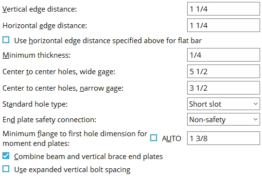
Vertical edge distance: The vertical distance from the horizontal edge (top or bottom) of the end plate to the center of the nearest hole.
|
Lv = vertical edge distance. |
Effect on connection design: The distance you enter here is the minimum vertical edge distance.. The actual designed vertical edge distance may be greater than the distance entered here.
Horizontal edge distance: The horizontal distance from the vertical edge of the plate to the center of the nearest hole.
|
Lh = horizontal edge distance. |
Effect on connection design: The distance you enter here is the minimum horizontal edge distance. The actual horizontal edge distance may be greater than the distance entered here.
Use horizontal edge distance specified above for flat bar: ![]() or
or ![]() .
.
If this box is checked (
), connection design attempts to use the horizontal edge distance that is specified above.
If the box is not checked (
), connection design will use your Connection design method's specified edge distance or 1 1/4 inch; whichever value is greater.
Minimum thickness: The minimum thickness of end plates that connection design uses when designing end plate connections.
|
t = thickness of end plate. |
Effect on connection design: The minimum thickness entered here applies to the connection design of end plates. Connection design uses thicker plate material than is entered here if such material is needed to meet connection design method guidelines and structural loading criteria.
Center to center holes, wide gage: The distance between the centers of the columns of holes on the plate. This distance should be between 5 1/2 and 7 1/2 inches in order for an end plate to be designed.
|
g = gage (center-to-center between columns of holes). |
Effect on connection design: The gage entered here applies during the connection design of end plates when
" Wide Gage " has been specified by the user for that end plate. For offset framing , connection design may increase this gage.End connection failure message: Valid connection gage: 5.5 to 7.5 in; 138 - 192 mm
Center to center holes, narrow gage: The distance between the centers of the columns of holes on the plate.
|
|
g = gage (center-to-center between columns of holes). |
Effect on connection design: The gage entered here applies to the connection design of end plates when " Narrow Gage " has been specified by the user for that end plate. For offset framing , connection design may increase this gage.
Standard hole type: Standard round or Short slot or Long slot or Oversized round or User slot #1 or User slot #2 .

Effect on connection design: Connection design determines the specific size and shape of the holes on the end plate according to the hole type that is entered here and the diameter of bolt that is used.
End plate safety connection: Non-safety or Safety-offset or Safety-notch . This applies when " Safety connection " is set to ![]() Connection specifications " on the Beam Edit window or at Home > Project Settings > Job > Auto Standard Connections or Home > Project Settings > Job > User Defined Connections . Connection design can create an end plate safety connection for two beams with end plates that frame to opposite sides of a supporting column web (or a beam web). In such a framing situation, the end plates on the two beams share bolts.
Connection specifications " on the Beam Edit window or at Home > Project Settings > Job > Auto Standard Connections or Home > Project Settings > Job > User Defined Connections . Connection design can create an end plate safety connection for two beams with end plates that frame to opposite sides of a supporting column web (or a beam web). In such a framing situation, the end plates on the two beams share bolts.
|
|
|
||||||
| The wide flange column in these illustrations is in stick form ( red ) so that its flange does not cover the end plates that frame to its web. The right beam's end plate is outlined in blue . | ||||||||
' Non-safety ' specifies that connection design design the two end plates to share all bolts.
' Safety-offset ' instructs connection design to attempt to vertically offset the end plates with respect to one another so that one row of bolts is not shared by the end plate of the opposing beam.
' Safety-notch ' configures connection design to create deeper end plates to accommodate an extra row of bolts and to perform a " Cope " on each plate so that each bolt in the top row of bolts is shared by the column and a different beam. The cut to the plate is on the far side of the beam that has its end plate specified on its left end ; the plate cut is on the near side of the other beam (which will have the end plate on its right end).
Minimum flange to first hole dimension for moment end plates: Auto or a user-entered distance . The " Flange to first hole dimension " is from the center of the hole to the nearest face of the flange (top or bottom face, whichever is closer).
|
f = flange to first hole. |
'
(12.7 mm) plus the flange weld " Weld size " if the flange weld is a fillet weld. If the flange weld is a groove weld with a reinforcement fillet weld, the reinforcement weld size will be used instead of the flange weld (minimum 1st hole dimension = bolt dia + 0.5 inch + reinforcement fillet weld size).'
Combine beam and vertical brace end plates: ![]() or
or ![]() . For an angle , W tee or channel vertical brace framing to a beam and column, connection design creates an end plate for the gusset-to-column interface if the beam connects to the column with an end plate. This option sets whether or not you want the end plates combined into a single end plate. It applies when ' Automatic ' is selected for " Combine beam/vbr end plates " in the "
. For an angle , W tee or channel vertical brace framing to a beam and column, connection design creates an end plate for the gusset-to-column interface if the beam connects to the column with an end plate. This option sets whether or not you want the end plates combined into a single end plate. It applies when ' Automatic ' is selected for " Combine beam/vbr end plates " in the " ![]() Connection specifications " for an end plate defined on the Beam Edit window or at Home > Project Settings > Job > Auto Standard Connections or User Defined Connections .
Connection specifications " for an end plate defined on the Beam Edit window or at Home > Project Settings > Job > Auto Standard Connections or User Defined Connections .
|
|

If this box is checked (
If the box is not checked (
Use expanded vertical bolt spacing: ![]() or
or ![]() . This applies when ' Automatic ' is the choice made to " Use expanded vertical bolt spacing " in the
. This applies when ' Automatic ' is the choice made to " Use expanded vertical bolt spacing " in the ![]() Connection specifications "
Connection specifications "
 |
 |
If this box is checked (
If the box is not checked (
A possible application: When an axial load (" Tension " or " Compression ") has been entered on the end of a beam with an end plate connection, expanded vertical bolt spacing can promote uniform loading across the connection bolts.
Another application: Expanded vertical hole spacing can also help to reduce fabrication costs by minimizing the number of rows of bolts in end plates.


|
|
OK (or the Enter key) closes this screen and applies the settings.
Cancel (or the Esc key) closes this screen without saving any changes.
Reset undoes all changes made to this screen since you first opened it. The screen remains open.
-
Settings applied here are for your current Fabricator . Each Fabricator in your current Job is a different collection of settings. This allows you to change to a different set of Standard Fabricator Connections each time you " Change Fabricator."
- These settings work in coordination with individual end plate "
 Connection specifications " to configure connection design for when the Beam Edit window > " Connection type " > " Input connection type " is ' End plate ' or ' Auto standard ' or ' User defined '.
- When creating an end plate, connection design checks the " Flats " list for an appropriate flat bar. If appropriate material is found, connection design uses that flat bar and takes into account the rolled edge when setting the " Horizontal edge distance ."
- End plate input specs (settings for defining end plates)
- Location (setting for defining a moment end plate)
- Bolt pattern (setting for defining a moment end plate)
- Setup of end plates (index)
- Connection guide (examples of end plates)

